It all begun as a straight forward job. When the EMU Emulator II HD plus arrived it was working and booting correctly and only one channel was not making any sound. Customers request was to replace all the buttons and sliders, install DREM Winchester HDD Emulator, fix the silent voice and put new display retrofit in there. I started with pots, sliders and display to have any further work eased by having reliable controls. All went well.
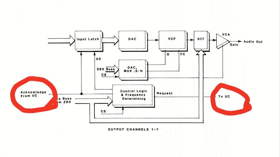
Next step was to find why the voice isn’t producing any sound. There was nothing on the output, I was releved there was also nothing at the input of the super rare switched capacitor filter chip as well as the rather expensive VCF chip. There was also nothing coming from the DAC and nothing coming in. I could see data at the input of the latch but there was no acknowledge signal triggering the latch. When I looked into how is the request generated I found one clock missing coming from Intel 8254 timer. Swapped the 8254s around and confirmed the culprit.

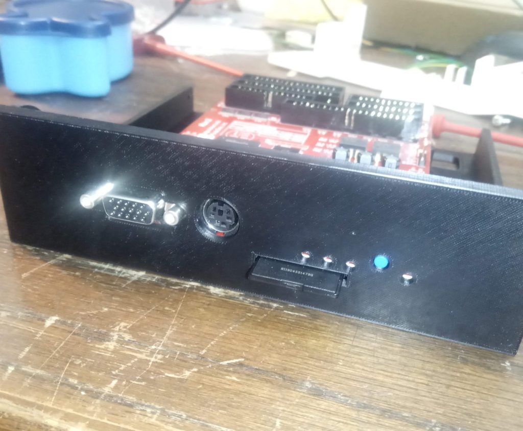
At that point all that was needed was to install the DREM and jobs done. I 3D printed the bracket, mounted it according to the instructions and I was hoping for it to work.

When the installation was done I was getting format error while I was able to run even HDD tests and they would return no errors, but as soon as I tried to access the data WRONG format message would appear.

cut the long story short there were two issues, I used 1:1 cable for the MFM data cable but it required the connector to be crimped the other way around. That took some head scratching to discover. However when I tried to access it I would still get wrong format message.

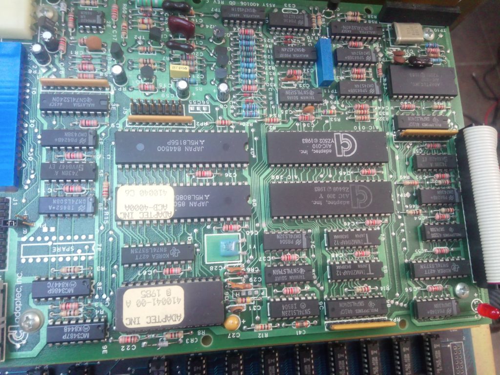
EMU II HD + has one of the earliest SCSI implementations from the time the standard was just being formed. Its not using full SCSI implementation to communicate with ADAPTEC ACB4000 Winchester HDD controller for its missing parity bit and ATN attention signal. Because of this it is not possible to just use SCSI to SD or SCSI HDD directly connected to the interface but the solution requires this ancient and rare Adaptec controller. With no documentation to hand and several custom Adaptec chips I was not giving it much hopes to be able to repair it but when I probed the HDD MFM balanced data lines with scope instead of the logic analyser I noticed one line is a bit dodgy. This was driven by chips very known to me from my endeavors with SSL 5000 series mixing console the RS422 drivers by Motorola. I replaced this and finally the whole thing was working and I took EMU to friend who has all the sound libraries so we could load this onto DREM SD card.
There I noticed the new display customer provided for installation suddenly lost few lines but it only did it after solid warm up. I ended up fatching different display but it wouldn’t work at all in this installation. I asked about this on Facebook group specialized on music gear display retrofits and luckily enough Ray Bellis, bless his cotton socks, chimed in with an idea to swap one of the IC’s in the display driver circuit from HCT version to LS version. Suddenly new display was working correctly. This has something to do with display pulse timing alteration. I do not fully understand why such a small speed variation can make it or break it but I’m happy it works.

Now with everything working it was finally time to close the lid, tighten the screws and give a good news to the owner.
Here came the trick, it would boot and work reliably with the lid open but it wouldn’t boot with the lid closed and it would even stop working whenever I tried to close the lid down. I tried all the possible things and connections which could be moving during the process but I could move press bend the PCB and all the connectors and cables as much as I wanted but it would still play reliably. When the lid was closed things would stop and the machine would freeze. I couldn’t understand what’s going on, why would just a proximity of the lid cause the CPU to crash.
Several hours of head scratching and brainstorming later I checked clock signal for the Scanner z80 CPU and I didn’t like what I’m seeing

Voltage was correct, frequency was correct but there was this ghosting as if it was jittering like mad. Then I noticed I could modulate the signal with getting my hand closer and further and that was finally something to focus on and track down. It was digital Theremin, I could make it dance like mad and I could even make the clock disappear just by waving my hand above the circuit boards in specific manner. This particular behavior was then tracked down to bad contact in one of the IC sockets in charge of the clock. Finally I was relieved I can finally close the machine down.

Beware Ostriches, EMU’s can be very mischievous and this one didn’t want to leave me. I closed the lid, turned it on and nothing!!!!
Display was just showing full block of squares and the boot sequence would hang after 3 clicks through the hard drive boot. I suspected while I fixed the one socket problem other may have happened elsewhere. After consulting the service manual I knew the problem is the Scanner CPU related so I checked all the data lines, address lines, clock, reset as well as all the other pins and all was behaving normally. There was nothing to suggest something is wrong, after a bit more sniffing around the components associated with scanner CPU boot process I noticed the CTC Z8430 is suppose to generate 3 timers on the output pins which are used as interrupts. I could only see one signal and others were all doing nothing. I once again checked this time on the CTC whether it has all the data lines all the address lines chip enable and all the other signals it needs to do the job and to my surprise all were OK. At this point it was not funny anymore, I tested different CTC but it was doing the same, all the input signals were correct but there was wrong output! The only explanation could be that there is something in the boot sequence before the CTC and its failure makes the CPU not to initialize this peripheral. The only way to find out was to use the analyzer and de-compile the Z80 instructions.


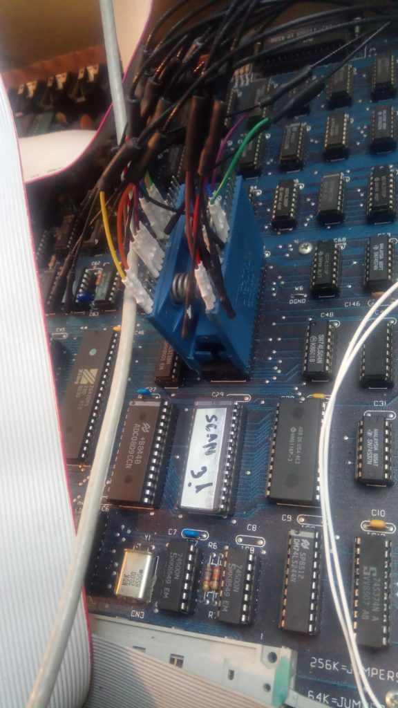
The boot sequence was quite long and because I only have 16 channel logic analyzer I could either decode instructions or addresses, I didn’t have enough channels to do full disassembly. After digging through about 500MB of data and going through the boot sequence step by step I finally found the problem. Somehow between the last working test and the lid closure contents of 2 bits within the Scanner EEPROM got corrupted and returned to FF state. How utterly unlikely! I burnt new Scanner EEPROM v 3.1 and everything is working reliably since.
Well fought mighty EMU, but you were defeated after all!

